- About Us
- What's New
- Products
- Markets & Applications
- Engineered Packages
- Service
- Training
- Literature
- Case Studies
Drive Selection
Home > Training > System Design > Drive Selection
 Selecting Your PumpDrive SelectionInlet DesignAccessory SelectionMounting and Location
Pumps are often powered by electric motors, engines, air motors, and hydraulic motors.
Horsepower is a measure of the rate at which work is being done from these power sources. Horsepower requirements vary from pump to pump based on flow and pressure requirements.
Cat Pumps literature references electric brake horsepower unless otherwise indicated.
Electric motors are defined by a number of specifications including voltage, amperage, rpm, phase (single or three), cycle (50 or 60 Hz), insulation class, motor type including TEFC, open drip, hazardous, sanitary wash-down, explosion proof, severe duty, premium efficiency (IEEC). Below is a formula for calculating electric brake horsepower.
Electric Brake Horsepower and Torque Formulas:
gpm (gallons/minute) x psi / 1460 x efficiency = Electric brake horsepower
Example: 30 gpm x 1200 psi / 1460 = 24.65 Hp (would use a 25 Hp motor)
Common electric horsepower sizes include 1.0, 1.5, 2.0, 3.0, 5.0, 7.5, 10, 20, 25, 30, 40, and 50 Hp.
We recommend you contact your motor supplier for advice on what products they would recommend for your application. This guide will focus on electric motor power pumping applications as this is the most frequently requested.
Gas/Diesel Horsepower
Gas and diesel horsepower can be calculated based on an electric horsepower calculation.
Gas powered = Electric horsepower x 1.4
Diesel powered = Use a range from straight line electric horsepower to electric horsepower x 1.4
Example: 5 gpm x 2500 psi / 1460 = 8.56 electric horsepower. Using gas to electric factor of 1.4, 8.56 Hp x 1.4 = 11.98 Hp (would use a 13 Hp gas engine)
Contact the engine supplier to confirm the horsepower requirement.
For proper engine selection it is recommended that the available continuous torque at the desired rpm is determined to properly size a combustion engine because combustion engines generate different levels of torque at different rpm’s and electric motors generate relatively constant torque.
Pumps can be direct driven by several means; hollow-shafted drives, bell housing and flexible coupler, gear box, or hydraulic motor. Air driven solutions are available but very inefficient. Contact Cat Pumps. Many of our pumps have a double sided crankshaft configuration. The pump can be driven by either side of the shaft while the unused side is covered with a shaft protector.
We recommend the pump to be operated with a forward rotation. With the pump manifold to your right, the crankshaft would turn clockwise (forward rotation). The forward direction allows proper internal lubrication of drive components. Pumps can be operated in reverse (backward rotation), but the oil level should be increased. For pumps equipped with a round site gauge, fill the crankcase oil between the dot and the top of the oil gauge window. For pumps equipped with a dipstick, the proper level is ½” above the normal mark.
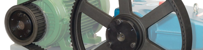
Belt driven pumps with pulleys or clutches are the most popular drive method for electric or gas driven systems.
Either V-belts or toothed (timing) belts can be used
Belts are inexpensive and simple to install and are available in a wide range of ratios
V-belts can shed dust into the atmosphere
Belts need to be checked for adjustment periodically and changed when worn
To determine the pulley combination for your system, read technical bulletin 003. Cat Pump offers clutch options 75 to 100 ft/lbs of torque on the 3CP through 15 frames.
Hollow shaft pumps are driven from the solid shaft on the electric motor or gas engine.
If a pump is run at the same speed as the motor or gas engine, a suitable bell housing and flexible coupler combination can be used to direct drive the pump. This combination uses a flexible urethane spider to transmit power from the motor shaft to pump shaft.
Cat Pumps offer a number of gear box selections primarily focused to pumps used in pressure washing applications.
An in-line gearbox is compact and needs no adjustment
Lubricating oil needs to be added then checked and changed periodically
Gear ratio must be chosen to give correct pump speed
Most gearboxes are available in a more limited range of ratios than belt drives
Hydraulic drives is a direct drive solution using flexible coupler
Motor speed can also be controlled using variable frequency drives (VFD). Cat Pumps can supply VFD’s on our custom units (Power Units). VFD’s are factory programmed and tested when sold as an accessory to a Power Unit. This is an ideal solution for customers interested in reducing operating costs by prolonging equipment life and using less energy. The device controls current and frequency (Hz) being supplied to the motor which regulates the motor’s rpm. Benefits include:
Replaces electric motor starter and/or soft start reducing power demands
Controlled starts and stops reducing mechanical wear compared to a standard motor starter
Can be operated with a P.I.D. feedback loop using a transducer to govern flow based on a predetermined pressure setting
Extends life of equipment by operating on demand only (when using a transducer and P.I.D. feedback loop)
“Sleep-mode” shuts down motor when system is not in use (when using a transducer and P.I.D. feedback loop)
Available for 50Hz and 60Hz motors
| What's New | ||||||||||||||||||||||||
|
||||||||||||||||||||||||
| Other Links |
| View our latest news |
| Sign up for E-mail Updates |
Literature |
|||
Technical Help |
|||
Troubleshooting |
|||
Contact UsTel: 01252 622031sales@catpumps.co.uk
|
|||
|
CERTIFIED MANAGEMENT SYSTEM - ISO 9001:2015 |
|||
|
|
|||
 |
|||
Home About Us What's New Service & Repair Markets & Applications Products Engineered Packages Literature Case Studies Sitemap
High Pressure Cleaning Equipment Cleaning and Wash Down Misting, Cooling & Fogging Pumps Energy, Oil & GasConstruction & QuarryingTransport & VehiclesAgriculture, Food & DrinkMetalworking & ManufacturingChemical & ProcessingWater, Environment & Waste