- About Us
- What's New
- Products
- Markets & Applications
- Engineered Packages
- Service
- Training
- Literature
- Case Studies
Inlet Design
.jpg)
Home > Training > System Design > Inlet Design
 Selecting Your PumpDrive SelectionInlet DesignAccessory SelectionMounting and Location
To jump to a section click on one of the links below:
Proper design of the pump inlet supply is critical to the success of any pumping system. The supply can be gravity, suction, or pressure fed depending on the pump selected. Improper supply to the pump will cause cavitation. Cavitation is the formation and collapse of gaseous pockets (cavities) in a liquid.
Cavitation occurs when a lack of liquid to the inlet causes vaporization in the low pressure chamber of the pump. When a vapor bubble is re-pressurized it quickly collapses supersonically and the shock wave erodes the surface it is on. This release of energy is created by the collapsing cavities, causes pitting and erosion of metallic or ceramic components. This process will create pump noise. The noise will be less pronounced when the pump is in bypass due to lower pressure changes. Piston pumps sound like the connecting rods are knocking or a bearing is bad. Plunger pumps sound similar to piston pumps, but most of the noise can be heard in the valve area of the head.
 |
|
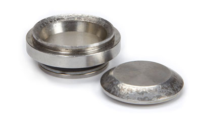
Cavitation can be identified by examining valves and valve |
Cavitation will decrease pump outlet flow and pressure as well because the pump doesn’t fully prime with liquid. Instead, the pump is attempting to pump a combination of liquid and vapor. Cavitation will cause shorter seal life, pitted valves, and manifolds. The short seal life is caused by the lack of lubrication (water is a lubricant in this scenario) increasing wear.
Another indication of cavitation is a decrease in the pumps flow rate. Because the pump doesn’t prime fully, the system pressure and flow becomes erratic (pump is trying to pump air).
A number of system conditions impact the risk of cavitation. If viscosity it too high, the pump will not prime (fill) completely causing cavitation. Cat Pumps recommends the viscosity not exceed 500cp (2500 SUS).
Restrictions to flow and pressure exist in any pumping system. Use of restrictive plumbing (i.e., small diameter plumbing, elbows) at the pump inlet can cause a loss of flow on the suction side of the pump causing pump cavitation. Inlet plumbing should be a minimum of one size larger than the pump inlet fitting (i.e., ¾” inlet fitting requires a 1” flexible reinforced hose for suction feed applications). Friction will also cause a loss of fluid pressure in the downstream pump components and plumbing. Vibration can also be abated by isolating the inlet and outlet of the pump using hoses. Avoid hard plumbing the pump to a piping system.
Clogged inlet filters can also impact effective pump priming due to the restriction caused by the contaminants in the filter element. We recommend filtering liquid before it’s supplied to the reservoir tank. Pump inlet filters will restrict flow to the pump inlet, especially when the filter element is blocked or restricted, causing pump cavitation. If an inlet filter is used, close monitoring by maintenance staff is required to prevent pump cavitation. Size the inlet filter to at least two times the flow rate of the pump.
Inlet pressure specifications for proper pump priming vary by the pump design. Ideally, all piston and plunger pumps should be pressure fed (piston pumps up to 40 psi and plunger pumps 60-70 psi based on the model). Inlet pressure reducing valves can be sized to reduce incoming water supply pressures if necessary. Excessive inlet pressure will cause premature wear of inlet manifold seals. A pump with worn inlet seals can draw air into the pump during priming causing cavitation and downstream pulsation under suction conditions. The same worn inlet seals will cause an external leak between the head and crankcase on a pressure fed system. When siphon feeding, piston pumps have - 8.5 psig suction. Some Plunger pumps draw no more than – 5.0 psig. Worn inlet seals will cause air entrainment into the pump causing cavitation.
High inlet temperature can also impact pump priming. Higher temperature fluids may require higher inlet pressure to avoid cavitation of the pump due to the liquid being closer to its boiling point. Follow the guidelines in Tech bulletin 002 for inlet recommendations when pumping higher temperature liquids. Reservoirs should be sized 6 – 10 times the rated flow (gpm) of the pump to ensure a constant, smooth flow the pump inlet. A properly sized reservoir also reduces heat generated in bypass mode. The reservoir should be baffled. Un-baffled reservoirs create turbulent flow causing air to enter the pump during operation and cause cavitation. A minimum of two baffles are recommend. A low flow shutoff valve is recommended to shut down the system in the event the reservoir runs low.
A fitting inlet plumbing leak may cause cavitation on a suction inlet system. Leaks can be caused by worn inlet seals, cracked pipes, hose and fittings not sealed using thread sealant.
Gravity Feed
The graphic below describes the sizing and design recommendations for the gravity feed tank. As indicated earlier, this tank design should be used for all feed methods.
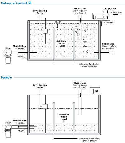
The reservoir should be 6-10 times the rated flow (gpm.lpm) of the pump.
Reservoirs should be baffled so turbulent flow is not created causing air bubbles which lead to cavitation.
A reservoir should have a minimum of two baffles. The supply line should be on the opposite side of the baffles and return line.
The tank should be covered to prevent contamination.
The tank should be mounted as high as possible above the pump. Ideally the liquid level (even when the tank is nearly empty) should be at least 6.5 feet (2 meters) higher than the pump. Applications closer to the liquid vapor pressure (i.e., hot water) require a higher static head.
A low-level switch or inlet pressure sensor should be installed to stop the pump should the tank level fall too low.
Suction Feed
Piston pumps have better suction lift performance than plunger pumps. Piston pumps have more suction lift because of their flow through design, continuous forward flow design, and mechanically actuated inlet valves. For this reason piston pumps are the preferred choice for suction feeding applications.
Our pumps are not self-priming so consider fitting a non-return foot valve at the bottom of the inlet feed pipe (be sure not to restrict the flow) and manually prime the pump before initial start-up or the inlet will lose prime when the pump is not running.
Exceeding suction limits of our pumps will starve the pump for liquid and cause cavitation.
Piston pumps: Not more than 8.5 psi suction (this is equivalent to drawing water vertically about 20 feet.
Plunger pumps: Not more than 5 psi suction on some models and flooded inlet on other models (consult data sheet for the pump model selected). 5.0 psi suction is equivalent to drawing water vertically about 11.5 feet.
1.0 psi = 2.31 ft. head of water
5.0 psi = 11.55 feet head of water (10.2” of mercury)
8.5 psi = 19.65 feed head of water (17.34” of mercury)
Note: Cat Pumps “Captive Acceleration Tube” cannot be used with low inlet pressure applications like suction feed. Piston and plunger pumps require liquid for lubrication when pumping or seals will overheat quickly and deteriorate. Select models using high temperature seals permit short duration run-dry operation, but pumps will not perform for extended time period without liquid. Contact Cat Pumps for assistance.
Pressure Feed
When the liquid is close to its vapor pressure or it’s not possible to provide an adequate head pressure, the pump can be pressure fed with a booster pump. A centrifugal pump is often used for this purpose.
For most pressure feed applications an inlet feed pressure of about 20 psi is adequate. The maximum inlet pressure for a plunger pump is 60-70 psi and 40 psi for piston pumps. The Cat Pumps “Captive Acceleration Tube” is recommended for pressure feed applications using a booster pumps. See the Inlet Plumbing section of this guide.
It is beneficial to interlock the primary pump with the booster pump so the primary pump cannot run dry if the booster pump is stopped, failed, or blocked.
It’s beneficial to install a low-pressure switch (set to 21-22 psi, 1.5 bar) at the inlet of the pump and interface it to the pumps motor starter when a pump inlet filter is used. This will protect the pump should the filter become blocked.
Inlet Plumbing
Do not hard plumb the supply to the pump inlet. The pump will vibrate during normal operation and vibrations can be transmitted though piping that can cause leakage of hard plumbed fittings. Instead, use a flexible inlet hose.
A plunger pump can be fed from either the side of the pump inlet manifold or both. Feeding the pump from both inlet fittings is recommended when the supply is poor and their might be a risk of pump cavitation. Consult with Cat Pumps to evaluate if a double feed method should be used.
A piston pump is fed at the bottom of the pump. The pump manifold can be inverted if a top feed design is desired.
Size the inlet plumbing to allow unrestricted flow into the pump so cavitation can be avoided. The plumbing should be a minimum of one pipe size larger than the pump inlet fitting size. Larger plumbing in this scenario is better.
Use as few fittings and changes of flow direction as possible. Use fully ported fittings (i.e., not thick-walled hydraulic fittings). Use large radius swept elbows or reinforced inlet hose. Do not use tight radius elbows.
When possible, install a straight pipe immediately before the pump inlet connection. The length should be ideally at least 20 times its diameter I.D.
Use the Cat Pumps “Captive Acceleration Tube” for applications using long inlet pipe runs or when pressure feed is used with a booster pump.
Install an inlet ball valve to the pump can be isolated from the supply should pump service be required. We recommend that all valves in the system are interlocked so the pump cannot run unless all valves are in their correct position.
If more than one pump will be supplied from the same supply tank, provide separate inlet pipes from the tank to the pump. If this is not possible, us a Y fitting or swept tee to branch off a single supply line to multiple pumps. Ensure the main feed line is of an adequate diameter to feed all pumps simultaneously.
To verify flow to the pump is sufficient to the pump, a simple supply flow check can be performed. To perform the check, follow the procedure below:
1. With the inlet ball valve closed, disconnect the feed pipe at the pump
2. With the supply tank nearly empty, open the inlet valve and time the flow into a graduated container. Appropriate caution should be taken doing this process with harmful liquids.
Ex. If the flow was 5 gallons in 15 seconds, the flow rate from the supply is four times the amount or 20 gpm. This flow rate should be twice the rated flow rate of the pump (10 gpm).
| What's New | ||||||||||||||||||||||||
|
||||||||||||||||||||||||
| Other Links |
| View our latest news |
| Sign up for E-mail Updates |
Literature |
|||
Technical Help |
|||
Troubleshooting |
|||
Contact UsTel: 01252 622031sales@catpumps.co.uk
|
|||
|
CERTIFIED MANAGEMENT SYSTEM - ISO 9001:2015 |
|||
|
|
|||
 |
|||
Home About Us What's New Service & Repair Markets & Applications Products Engineered Packages Literature Case Studies Sitemap
High Pressure Cleaning Equipment Cleaning and Wash Down Misting, Cooling & Fogging Pumps Energy, Oil & GasConstruction & QuarryingTransport & VehiclesAgriculture, Food & DrinkMetalworking & ManufacturingChemical & ProcessingWater, Environment & Waste